ROS URDF Tutorial: Custom robot
1. Introduction
This tutorial explains the basics of how to describe industrial robots in ROS and how to use the created kinematic models. You will learn about the Unified Robot Description Format (URDF). The tutorial will inform about how to create a robot model and how to visualize your robot.
2. Create an URDF file
A URDF file is created in the XML format. URDFs contain information about the robot links and joints. For detailed information about this format check the following link: http://wiki.ros.org/urdf/XML
Figure 1 shows a simple kinematics that can be built using URDF.
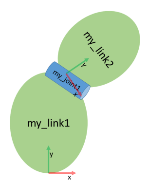
Figure 1: Serial kinematics sketch
It is a simple kinematics existing of two links connected via a continuous rotating joint.
2.1 Create the tree structure
The robot in Figure 1 is a tree structure. Let’s start very simple, and create a description of that
tree structure, without worrying about the dimensions etc. Fire up your favorite text editor,
and create a File called robot.urdf :
 1<?xml version="1.0"?>
 2<robot name="custum_robot">
 3    <!-- Outside world-->
 4    <link name="world" />
 5    <!-- Base of the robot -->
 6    <link name="base_link" />
 7
 8    <joint name="base_joint" type="fixed">
 9        <parent link="world"/>
10        <child link="base_link"/>
11    </joint>
12
13    <!-- Add a continuosly rotating joint connecting the
14    fixed base to the moveable link -->
15
16    <joint name="joint1" type="continuous">
17        <parent link="base_link"/>
18        <child link="link1"/>
19    </joint>
20
21    <!-- Moveable link-->
22    <link name="link1"/>
23</robot>
So, just creating the structure is very simple! Now let’s see if we can get this urdf le parsed. Run the check command to see if the syntax is correct:
$ check_urdf robot.urdf
2.2 Add dimensions
To add dimensions to our tree, we have to specify the offset from a link to the joint(s) of its children. To accomplish this, we will add the field <origin> to each of the joints. Joint1 is offset in the Z-direction from link1. So, we need to add the following <origin> element:
<origin xyz="0 0 0.5" rpy="0 0 0"/>
Repeat this for every continuous joint element of the URDF. Now run it through the parser and check for syntax with the command shown above.
2.3 Completing the kinematics
We need to specify around which axis the joints rotate. Once we add that, we actually have a full kinematic model of this robot! We need to add the <axis> element to each joint. The axis specifies the rotational axis in the local frame.
Joint1, you see it rotates around the positive X-axis. So, simply add the following to the joint element:
<axis xyz="1 0 0" />
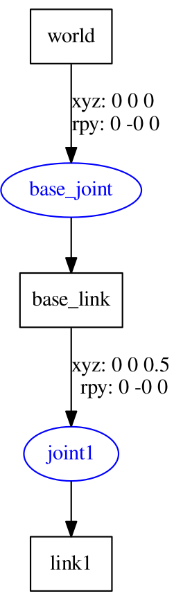
Repeat this for every continuous joint element of the URDF. Now run it through the parser and check for syntax with the command shown above. That’s it, you created your first URDF robot description! kinematic chain described in the URDF using graphviz, one could display the created kinematic chain:
$ urdf_to_graphiz robot.urdf
$ evince custom_robot.pdf
To visualize and control this model, run the following command:
roslaunch urdf_tutorial display.launch model:=robot.urdf
However now this will also pop up a GUI that allows you to control the values of all the non-fixed joints. Play with the model and see how it moves. Then, we can take a look at how we accomplished this.
As you move the sliders around in the GUI, the model moves in Rviz. How is this done? First the GUI parses the URDF and finds all the non-fixed joints and their limits.
Then, it uses the values of the sliders to publish sensor_msgs/JointState messages. Those are then used by
robot_state_publisher to calculate all of transforms between the different parts. The resulting
transform tree is then used to display all of the shapes in Rviz.
3. Create a workcell with XACRO
Note
Follow bellow steps before creating a workcell with XACRO.
$ mkdir -p ~/moveit_ws/src
$ cd ~/moveit_ws/src
$ git clone --recurse-submodules https://github.com/ROSinTraining/ros_manipulation_day4.git
$ cd ..
$ rosdep install --from-paths --ignore-src src -y
$ catkin_make
$ source devel/setup.bash
$ cd src
$ catkin_create_pkg myfirst_urdf rospy roscpp
$ mkdir -p myfirst_urdf/urdf && cd myfirst_urdf/urdf
$ touch workcell.xacro
In this exercise, we’ll mount a UR5 robot on a table using XACRO tools.
Create a skeleton of the model with an empty world link (edit
workcell.xacro):<?xml version="1.0"?> <robot xmlns:xacro="http://ros.org/wiki/xacro" name="ur5" > <!-- Setup empty world --> <link name="world" /> </robot>
Locate the xacro file that implements table macro and include it in your newly created
workcell.urdf.xacro. Add this include line near the top of your file, beneath the<robot>tag.<xacro:include filename="$(find tutorial_commons)/urdf/table_ur.urdf.xacro" />
Including the table_ur.urdf.xacro file does not actually create a table in our URDF model. It defines a macro, but we still need to call the macro to create the links and joints.
<xacro:table prefix="" parent="world" >
    <origin xyz="0.0 0.0 0.0" rpy="0.0 0.0 0.0" />
</xacro:table>
Now locate the xacro file that implements the UR5 macro and include it as well:
<xacro:include filename = "$(find ur_description)/urdf/ur5.urdf.xacro"/>
Most macros will take a “prefix” parameter to allow a user to create multiple instances of said macro. It’s the mechanism by which we can make the eventual URDF element names unique, otherwise we’d get duplicate link names and URDF would complain. Note the use of the prefix tag, as discussed above.
<xacro:ur5_robot prefix= "" joint_limited="true"/>
We have to connect the rest of your world to the robot’s macro. This means you have to look at the macro and see what the base link is. The given macro follows the ROS-Industrial standard, that says that base links are named
base_linkand the table’s link is calledplatform.Connect the UR5 base_link to given static geometry of the table with a fixed link.
<joint name="world_joint" type="fixed">
    <parent link="platform"/>
    <child link="base_link"/>
    <origin xyz= "${table_width/2} ${table_length/2} ${table_height}" rpy="0 0 0"/>
</joint>
Convert the XACRO to URDF with the following command.
Hint
Do not forget to
catkin_makewhenever you create a new package inside your workspace. Also, do not forget to source your workspace in every new terminal.$ rosrun xacro xacro -- inorder -o workcell.urdf workcell.urdf.xacro
Now run it through the parser and check for syntax with the command shown in the previous section. You can also display the URDF and control the joints with the command shown in the previous section.